• home

Bipolar Power supply for Battery Instruments Circuit Diagram

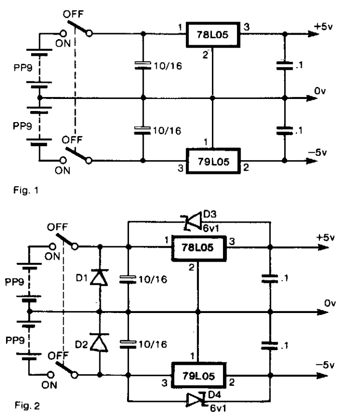
Bipolar Power supply for Battery Instruments Circuit Diagram. To generate regulated ± 5-V supplies from a pair of dry batteries, the circuit of Fig. 1 is commonly used. In order to give protection from inadvertent reverse connection of a battery, a diode in series with each battery would produce an unacceptable voltage drop. The more effective approach is to fit diodes Dl and D2 as shown in Fig. 2, in parallel with each battery. 

When the supply is switched off, there is the risk of a reverse bias being applied across the regulators, if there is significant inductance or capacitance in the load circuit. Diodes across the regulators prevent damage. When the power supply is switched on, the two switches do not act in unison. There is a probability that one or the other regulators will be latched hard off by the other. To prevent this, D3 and D4 are Zener diodes so that ± 5-V rails are pulled up by the batteries until the regulators establish the correct levels.

 Bipolar Power supply for Battery Instruments Circuit Diagram


Bipolar Power supply for Battery Instruments Circuit Diagram

78S09 9 Volt 2 Amp Power Supply

 All the work is done by the regulator. The 78S09 can deliver up to 2 amps continuous output whilst maintaining a low noise and very well regulated supply.
The circuit will work without the extra components, but for reverse polarity protection a 1N5400 diode is provided at the input, extra smoothing being provided by C1. The output stage includes C2 for extra filtering, if powering a logic circuit than a 100nF capacitor is also desirable to remove any high frequency switching noise.

 
78S09 9 Volt 2 Amp Power Supply 

Variable DC Power Supply Rise

This project provides the schematic & the parts list needed to construct a simple DC Power Supply from an input power supply of 7-20 V AC or 7-30V DC. This project will come in handy in case you use plenty of batteries for your basic electronics project.

Two DC voltage outputs are available; is a fixed regulated 5V for TTL use. The other output is variable from 5V upwards. The maximum output voltage depends on the input voltage. The specified maximum input DC voltage to the regulator is 35V. The maximum input voltage must be two volts higher than the regulated output voltage.


The DC Power Supply circuit is based around the 7805 voltage regulator. Its only three connections input, output & ground & it provides a fixed output. The last digits of the part number specify the output voltage, e g. 05, 06, 08, ten, 12,15, 18, or 24. The 7800 series provides up to one amp load current & has on-chip circuitry to close down the regulator if any attempt is made to operate it outside its safe operating area.It can be seen that theres in fact separate circuits in this power supply. 7805 is directly connected as a fixed 5V regulator. The second 7805 has a resistor divider network on the output. A variable 500 ohm potentiometer is used to vary the output voltage from a maximum of 5V up to the maximum DC voltage depending on the input voltage. It will be about 2V below the input DC voltage.

The capacitor across the output improves transient response. The giant capacitor across the input is a filter capacitor to help smooth out ripple in the rectified AC voltage. The larger the filter capacitor the lower the ripple.

For tiny applications the heat sinks wont be needed. The tab on the regulator will dissipate 2W at 25 o C in air. (This is equivalent, for example, to an input voltage of 9V, an output of 5V & drawing 500 m A.) However, as your projects get bigger they will draw more current from the power supply and the regulators will operate at a higher temperature and a heat sink will be needed. You can basically add voltage & current meters to it and put it in to an appropriate plastic case connected to a transformer.


Trouble Shooting Procedure

An LED has been put in to the output of the fixed 5V regulator to indicate that the circuit is working. Poor soldering is the most likely reason that the circuit does not work. Check that all the soldering is done properly. Check that all parts are in their correct position on the PCB. Other items to check are to make sure that the regulators, electrolytic capacitor & bridge rectifier are inserted in the correct orientation.

0 30 Volt Power Supply

linear power supply, shown in the schematic, provides 0-30 volts, at one amp, maximum, using a discrete transistor regulator with op amp feedback to control the output voltage. The supply was constructed in 1975-6 & has a constant current mode that is used to recharge batteries.


With reference to the schematic, lamp, LP2, is a power on indicator. The other lamp (lower) lights when the unit reaches its preset current limit. R5, C2, & Q10 (TO-3 case) operate as a capacitor multiplier. The 36 volt zen-er across C2 limits the maximum supply voltage to the op amps supply pins. D5, C4, C5, R15, & R16 provide a tiny amount of negative supply for the op amps so that the op amps can operate down to zero volts at the output pins (pins 6). A more modern design might eliminate these four parts & use a CMOS rail-to-rail op-amp. Current limit is set by R3, D1, R4, R6, Q12, R10, & R13 providing a bias to U2 that partially turns off transistors Q9 & Q11 when the current limit is reached. R4 is a front panel potentiometer that sets the current limit, R22 is a front panel potentiometer that sets the output voltage (0-30 volts), & R11 is an internal trim-pot for calibration. The meter is a one milliamp meter with an internal resistance of 40 ohms. Switch S1 determines whether the meter reads 0-30 volts, or 0-1 amp.


A more new circuit might use a single IC regulator, such as the MC78XX, or MC79XX series, immediately after the half wave rectifier, to replace about 30 parts, or at least a high precision zen-er diode to replace D10 as the voltage reference. The LM4040 is such voltage reference & has excellent stability over temperature. IC regulators such as the MC78XX series may finally become obsolete as newer IC regulators are designed, however, discrete transistors, op-amps, & zeners are more generic, have an extended production lifespan, & permit the designer to demonstrate that they understands the principles of linear regulated power supply operation.

10 Amp 13 8 Volt Power Supply

This is a design for power supply. This circuit is using LM723 for voltage regulator. This is a simple design circuit. This is the figure of the circuit.


The circuit even has a current limiting feature which is a more reliable system than most commercial units have. The circuit uses 3 pass transistors which must be heat sink. Resistor R9 allows the fine tuning of the voltage to exactly 13.8 volts and the resistor network formed by resistors R4 through R7 controls the current limiting. The LM723 limits the current when the voltage drop across R5 approaches .7 volts. To reduce costs, most commercial units rely on the HFE of the pass transistors to determine the current limiting. The fault in that system is that the HFE of the pass transistors actually increases when the transistors heat up and risks a thermal runaway condition causing a possible failure of the pass transistors. Because this circuit samples the collector current of the pass transistors, thermal runaway is not a problem in this circuit making it a much more reliable power supply.

The only adjustment required is setting R9 to the desired output voltage of anywhere between 10 and 14 volts. You may use a front panel mounted 1K potentiometer for this purpose if desired. Resistor R1 only enhances temperature stability and can be eliminated if desired by connecting pins 5 and 6 of IC-1 together. Although it really isnt needed due to the type of current limiting circuit used, over voltage protection can be added to the circuit by connecting the circuit of Figure 2 to Vout. The only way over voltage could occur is if transistors Q2 or Q3 were to fail with a collector to emitter short. Although collector to emitter shorts do happen, it is more much more likely that the transistors will open up when they fail.

12 Volt Off Line Power Supply

This is a simple circuit for switching power supply. This circuit is using converter concept. This is the figure of the circuit.


This circuit can work over an universal input AC line voltage range 90-240 VAC and provides 12 VDC output when over 4A loaded. Line and load regulation is better than 0,5%. This circuit has over current, over temperature, over voltage protection. The output ripple is approximately 0,2Volt peak to peak.

Dual rail Variable DC Power Supply

Simple add-on for a single-rail supply, ±2.5V to ±15V output


This design was conceived as an add-on for the Variable DC Power Supply, a very successful circuit posted to this website. This simple unit provides a dual-rail variable output ranging from ±2.5V to ±15Vdc with precise tracking of the positive and negative output voltages, still retaining the current limiting and short-proof capabilities of the "master" circuit. As the purpose of such a dual-rail design is to supply experimental or under-repair circuits, the maximum current output delivered was deliberately kept to about 500 - 600mA per rail, thus avoiding the use of expensive power transistors and complex circuitry.


Circuit Diagram:


Dual-rail Variable DC Power Supply Circuit Diagram


Parts:

R1 = 4.7K-1/2W
R1 = 4.7K-1/2W
C1 = 100nF-63V
C2 = 220µF-25V
C3 = 220µF-25V
C4 = 100nF-63V
C5 = 100nF-63V
Q1 = BD437
Q2 = BD438
IC1 = LM358


Notes:
  • The circuit can be placed into the existing Variable DC Power Supply metal cabinet.
  • Q1 and Q2 must be mounted on heatsinks. Usually, bolting them to the metal case (through insulating washers etc.) proved effective.
  • The full ±15V output can be achieved only if the secondary winding of the supply Transformer used in the Variable DC Power Supply is rated at 48V minimum (center tapped).
  • When using this circuit, please set the Current-limit control (P1) of the Variable DC Power Supply to any value comprised in the 50mA - 1A range but not higher.
  • The second Op-amp (IC1B) contained in the LM358 chip was not used, but its input pins were tied to the negative supply and the output was left open.


Source : www.redcircuits.com