• home

Bipolar Power supply for Battery Instruments Circuit Diagram

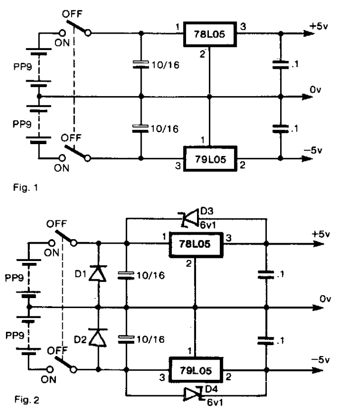
Bipolar Power supply for Battery Instruments Circuit Diagram. To generate regulated ± 5-V supplies from a pair of dry batteries, the circuit of Fig. 1 is commonly used. In order to give protection from inadvertent reverse connection of a battery, a diode in series with each battery would produce an unacceptable voltage drop. The more effective approach is to fit diodes Dl and D2 as shown in Fig. 2, in parallel with each battery. 

When the supply is switched off, there is the risk of a reverse bias being applied across the regulators, if there is significant inductance or capacitance in the load circuit. Diodes across the regulators prevent damage. When the power supply is switched on, the two switches do not act in unison. There is a probability that one or the other regulators will be latched hard off by the other. To prevent this, D3 and D4 are Zener diodes so that ± 5-V rails are pulled up by the batteries until the regulators establish the correct levels.

 Bipolar Power supply for Battery Instruments Circuit Diagram

Bipolar Power supply for Battery Instruments Circuit Diagram

VU and PPM Meter Circuit for Audio

A VU (Volume Unit) meters used to be the mainstay of audio metering system. The Peak Program Meter (PPM) is notoriously bad at showing the peak signal level. This is a circuit that have function same of the explanation in above. In this circuit, the amplifier/rectifier is a simple LM1458 or similar dual op-amp, and buffers the rectifier circuit. This is the figure of VU meter;


The principle of the VU meter is a single diode is used in some, but the better ones will generally use a tiny selenium bridge rectifier or a germanium diode bridge. A capacitor is show, few budget VU meters will include it. As a result, the meter movement itself is uncontrolled in most of these meters, so overshoot is often huge, and the reading is almost useless. Because of the diode forward voltage, many of these meters also fail completely to register low level signals (< -20 dB). In figure 2, is shown of the meters ballistic control for the VU meter. The principle of this circuit is the values of R6, C1, C2 and C3 may need to be adjusted, depending upon the ballistics of the meter movement you use. Because meters vary so widely in this respect, it is only possible to provide representative values, although they should work quite well in practice. In order to get exact VU meter ballistics, it will be necessary to test the meter with a 300ms burst waveform at full scale (+3VU). It should reach 99% of full scale with up to 1% of overshoot before dropping back to zero. If we want to know about the result of the VU meter testing, we must make the circuit.

Music On Hold for Telephones

Here is a simple circuit for music-on-hold with automatic shut off facility. During telephone conversation if you are reminded of some urgent work, momentarily push switch S1 until red LED1 glows, keep the telephone handset on the cradle, and attend to the work on hand. A soft music is generated and passed into the telephone lines while the other-end subscriber holds. When you return, you can simply pick up the handset again and continue with the conversation. The glowing of LED1, while the music is generated, indicates that the telephone is in hold position. As soon as the handset is picked up, LED1 is turned off and the music stops.

Music-On-Hold for Telephones Circuit diagram :

Music-On-Hold for-Telephones-Circuit-Diagram


Normally, the voltage across telephone lines is about 50 volts. When we pick up the receiver (handset), it drops to about 9 volts. The minimum voltage required to activate this circuit is about 15 volts. If the voltage is less than 15 volts, the circuit automatically switches off. However, initially both transistors T1 and T2 are cut off. The transistor pair of T1 and T2 performs switching and latching action when switch S1 is momentarily pressed, provided the line voltage is more than 15 volts, i.e. when the handset is placed on the cradle. Once the transistor pair of TI and T2 starts conducting, melody generator IC1 gets the supply and is activated. The mu-sic is coupled to the telephone lines via capacitor C2, resistor R1, and the bridge rectifier.

With the handset off-hook after a ring, momentary depression of switch S1 causes forward biasing of transistor T2. Mean-while, if the handset is placed on the cradle, the current passing through R1 (connected across the emitter and base terminals of pnp transistor T1) develops enough voltage to forward bias transistor T1 and it starts conducting. As a consequence, output voltage at the collector of transistor T1 sustains for-ward biasing of transistor T2, even if switch S1 is released. This latching action keeps both transistors T1 and T2 in conduction as long as the output of the bridge rectifier is greater than 15 volts. If the handset is now lifted off-hook, the rectifier output drops to about 9 volts and hence latching action ceases and the circuit automatically switches off.

EFY lab note. The value of resistor R2 determines the current through resistor R1 to develop adequate voltage (greater than 0.65 volts) for conduction of transistor T1. Hence it may be test selected between 33 kilo-ohms and 100 kilo-ohms to obtain instant latching.) The total cost of this circuit is around Rs 50.

Source : http://www.ecircuitslab.com/2012/02/music-on-hold-for-telephones.html