Description.


Notes.
A different type of remote control circuit employing ultrasonic signals is given here.
The
transmitter part of the circuit is build around IC1(NE 555).The IC1 is
wired as an astable multi vibrator operating at 40KHz.The output of
IC1 is amplifier the complementary pair of transistors ( Q1 & Q2)
and transmitted by the ultrasonic transmitter K1.The push button switch
S1 is used the activate the transmitter.
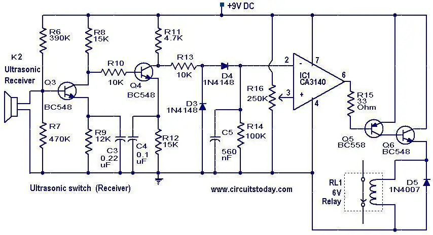
The receiver uses an ultrasonic sensor transducer
(K2) to sense the ultrasonic signals. When an ultrasonic signal is
falling on the sensor, it produces a proportional voltage signal at its
output. This weak signal is amplified by the two stage amplifier
circuit comprising of transistors Q3 and Q4.The output of the amplifier
is rectified by the diodes D3 & D4.The rectified signal is given
to the inverting input of the opamp which is wired as a comparator.
When ever there is an ultrasonic signal falling on the receiver, the
output of the comparator activates the transistors Q5 & Q6 to drive
the relay. In this way the load connected via the relay can be
switched. The diode D5 is used as a free wheeling diode.
Circuit diagram with Parts list.(K2) to sense the ultrasonic signals. When an ultrasonic signal is
falling on the sensor, it produces a proportional voltage signal at its
output. This weak signal is amplified by the two stage amplifier
circuit comprising of transistors Q3 and Q4.The output of the amplifier
is rectified by the diodes D3 & D4.The rectified signal is given
to the inverting input of the opamp which is wired as a comparator.
When ever there is an ultrasonic signal falling on the receiver, the
output of the comparator activates the transistors Q5 & Q6 to drive
the relay. In this way the load connected via the relay can be
switched. The diode D5 is used as a free wheeling diode.


Notes.
- Assemble the the circuit on good quality boards.
- The switch S1 can be a push button switch.
- The ICs must be mounted on holders.
- The transmitter can be powered from a 9V PP3 battery.
- For
low power applications the receiver can be also powered from a 9V PP3
battery.For high power applications, use a 9V DC power supply. - The preset R16 can be used to adjust the sensitivity of the receiver.
- The frequency of the ultrasonic signal can be varied by adjusting the preset R17.Adjust it for optimum performance.


0 comments:
Post a Comment
Note: Only a member of this blog may post a comment.