Fuse Box Ford 2008 F150 Passenger Compartment Diagram - Here are new post for Fuse Box Ford 2008 F150 Passenger Compartment Diagram.

Fuse Panel Layout Diagram Parts: Brake shift interlock solenoid, Fog lamp relay, Electrochromatic mirror, Heated seats, BSM, Compass, RSS (Reverse Sensing System), Power Rail, Delayed accessory power for audio, Run/Accessory Wipers, Instrument cluster, Audio for XL/STX, Parklamps, Body Security Module (BSM), Instrument Panel Illumination, Radio (Start signal), Heated Mirros, Switch Indicators, Fuel Pump Relay, Fuel Injectors, Injector Sense, Trailer Tow back up Lamps relay, Trailer tow parklamp relay, A/C Clucth, 4×4 solenoid, PCM relay coil, Climate control module power, Flasher relay, Back up lamp and Dyatime Running Lamps (DRL) relay coil, A/C pressure switch, Redundant speed control switch, Heated PCV (5.4L). ABS, Overdrive cancel, Memory seats and pedals. DVD battery power, Power fold mirror, Keep alive memory for Powertrain Control Module (PCM) and Climate Control Module, Cluster, Battery saver power for demand lamps, Cluster airbag warning lamp, Vapor Management Valve (VMV), A/C clucth relay, Canister vent, Heated Exhaust Gas Oxygen (HEGO) sensors # 11 and # 21, Stop/Turn Lamps, ABS, T/T electric brake module, PCM (BOO signal), turn signal mirros, CHSML, Power Mirrors, Variable Cam Timing (VCT), Heated Positive Crankscase Ventilation (PCV) valve (4.2L engine), CID sensor (4.2L engine), 4.6L/4.2L, EGERFlex fuel, power door lock switch and moon roof switch illumination, CMCV, Mass Air Flow (MAF) sensor, Passenger Airbag Deactivation (PAD) warning lamp.
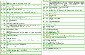
Fuse Box Ford 2008 F150 Passenger Compartment Diagram


Fuse Panel Layout Diagram Parts: Brake shift interlock solenoid, Fog lamp relay, Electrochromatic mirror, Heated seats, BSM, Compass, RSS (Reverse Sensing System), Power Rail, Delayed accessory power for audio, Run/Accessory Wipers, Instrument cluster, Audio for XL/STX, Parklamps, Body Security Module (BSM), Instrument Panel Illumination, Radio (Start signal), Heated Mirros, Switch Indicators, Fuel Pump Relay, Fuel Injectors, Injector Sense, Trailer Tow back up Lamps relay, Trailer tow parklamp relay, A/C Clucth, 4×4 solenoid, PCM relay coil, Climate control module power, Flasher relay, Back up lamp and Dyatime Running Lamps (DRL) relay coil, A/C pressure switch, Redundant speed control switch, Heated PCV (5.4L). ABS, Overdrive cancel, Memory seats and pedals. DVD battery power, Power fold mirror, Keep alive memory for Powertrain Control Module (PCM) and Climate Control Module, Cluster, Battery saver power for demand lamps, Cluster airbag warning lamp, Vapor Management Valve (VMV), A/C clucth relay, Canister vent, Heated Exhaust Gas Oxygen (HEGO) sensors # 11 and # 21, Stop/Turn Lamps, ABS, T/T electric brake module, PCM (BOO signal), turn signal mirros, CHSML, Power Mirrors, Variable Cam Timing (VCT), Heated Positive Crankscase Ventilation (PCV) valve (4.2L engine), CID sensor (4.2L engine), 4.6L/4.2L, EGERFlex fuel, power door lock switch and moon roof switch illumination, CMCV, Mass Air Flow (MAF) sensor, Passenger Airbag Deactivation (PAD) warning lamp.


.jpg)

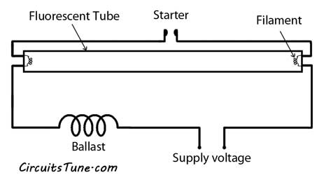
 Simple Emergency Light Circuit Diagram